








| Geräteparameter | ||
|---|---|---|
| Parametername | Specification/Parameters | Notes |
| Overall Length | Retracted: 525 mm Ausgefahren: 1500 mm |
Standard |
| Tragfähigkeit | 50 kg/m | Standard |
| Geschwindigkeit | 40 m/min | 1 Minute |
| Breite | 500/600/800 mm | Other sizes available on request |
| Roller | Diameter: 50 mm Thickness: ≥1.5T |
Verzinkt/201 |
| Wellenkern | Q235 | Standard |
| Telescoping Ratio | 1: 3 | Standard |
| Legs (Main H Frame) | Cross-sectional size: 35 × 35 mm Thickness: ≥1.3T Material: 201 |
Standard |
| Support Legs | Cross-sectional size: 30 × 30 mm Thickness: ≥1.3T Material: 201 |
Konstruktion der Manschette / höhenverstellbar |
| Equipment frame steel wall thickness | ≥3.5T, Q345 | |
| Zubehörparameter | ||
| Parametername | Specifications / Parameters | Anmerkungen |
| Reduzierstück | 120 W | 1 unit configured per 1.5 m |
| VFD | 0.75 kW / 1.5 kW / 2.2 kW | Nach Länge konfiguriert |
| Fahrmodus | O-belt | Verschleißfest |
| Rated voltage | 380/220 V | Standard |
| Control panel | Vorwärts/Rückwärts / Not-Aus / Drehzahlregelung | |
| Electrical control box | In Übereinstimmung mit den einschlägigen nationalen Normen | |
| Casters | 4 in Wheel face width: 30 mm Radhöhe: 120 mm |
With full brakes, meeting load-bearing design requirements |
| Weitere Parameter | ||
| Parametername | Specifications / Parameters | Anmerkungen |
| Equipment electrical control box and wiring | Use 1.5 sq. mm wire and parallel wiring. | Standard wiring required / power line leakage protection |
| Anti-static | Multiple conductive materials built in | |
| Produktabmessungen | ||
| Effektive Breite | Gesamtbreite der Maschine | Weight per section |
| 500 mm | 655 mm | 31 kg |
| 600 mm | 755 mm | 36 kg |
| 800 mm | 955 mm | 41 kg |
| Sonstige Parameter | ||
| 1: Three standard bracket options are available: 460-680 / 550-820 / 750-1200 / 900-1500; other sizes require customization. | ||
| 2: 10 rollers per section. | ||
| 3: The spacing between rollers is 110 mm (when using spacing rods, the spacing is 50 mm). | ||
| 4: For a 90-degree turn, two sections are the best choice. | ||
| 5: For a 180-degree turn, three sections are the best choice. | ||
| Garantie | ||
| Artikel | Zeitraum | Notes |
| Machine Body Warranty Period | 12 Monate | |
| The conveyor body and motor are warranted for one year, and the drive belt is warranted for six months.
During the warranty period, if a part has a quality issue due to non-human damage, we will provide a replacement part free of charge. However, as international shipping is involved, the related freight cost shall be borne by the customer. If the equipment or parts are damaged due to improper manual operation, improper use, improper maintenance, or if the issue occurs outside the warranty period, both the cost of replacement parts and the shipping cost shall be borne by the customer. For overseas orders, the warranty period is calculated from the bill of lading date; for domestic orders, the warranty period is calculated from the date of goods delivery or arrival. |
||
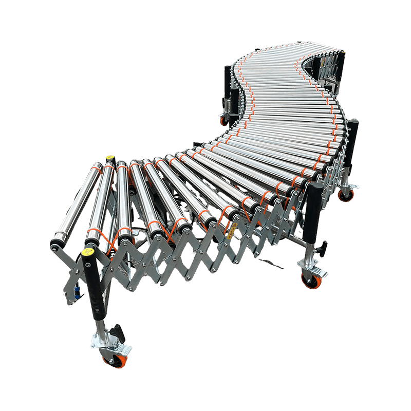
Serie der angetriebenen Rollenförderer
Rollenförderer mit O-Riemenantrieb
The O-shaped belt Powered Roller Conveyor uses an O-shaped belt drive design to achieve smooth and efficient cargo conveyance. The motor spacing is 1, 500 mm, the conveying load is 80 kg per meter, and the stable movement of goods is ensured. It is suitable for warehouses, factories, and logistics facilities, providing a reliable powered conveying solution. It can be freely telescoped and turned.
Geschwindigkeit
0,3–40 m/min, stufenlose Drehzahlregelung
Tragfähigkeit
80 kg/m
Effektive Breite
500/600/800/1000 mm
Rückzugsverhältnis
1:2.9
Geeignete Güter (empfohlenes Höchstgewicht pro Stück)
O-Belt Powered Roller Conveyor Maximum weight per item (reference)
Das tatsächliche Höchstgewicht hängt von den jeweiligen Betriebsbedingungen und der Konfiguration ab.
| Art der Ware | Maximales Gewicht (pro Stück) |
|---|---|
Kunststofffass | 30 kg/pcs |
Metallfass | 30 kg/pcs |
Karton | 30 kg/pcs |
Rolle | 30 kg/pcs |
Kunststofffass
Maximales Gewicht (pro Stück)
30 kg/pcs
Metallfass
Maximales Gewicht (pro Stück)
30 kg/pcs
Karton
Maximales Gewicht (pro Stück)
30 kg/pcs
Rolle
Maximales Gewicht (pro Stück)
30 kg/pcs
Produktoptionen
O-Belt Powered Roller Conveyor Product Options
Wählen Sie entsprechend den örtlichen Gegebenheiten geeignete Sonderausstattungen, Bauteile und Zusatzkonfigurationen aus.
Kein Bild verfügbar
#1 Das Gehäuse besteht aus Edelstahl 304.
Kein Bild verfügbar
#2: Auf einen wasserdichten Motor umgerüstet.
Kein Bild verfügbar
#3 Umrüstung auf explosionsgeschützte Motoren
Kein Bild verfügbar
#4 Wasserdichter Schaltschrank
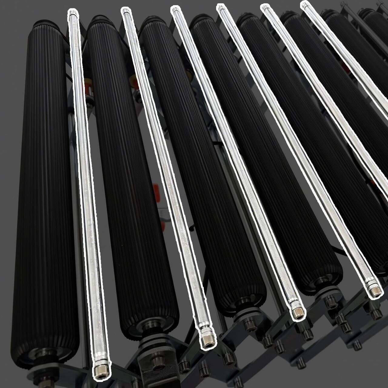
#5 Distanzleiste
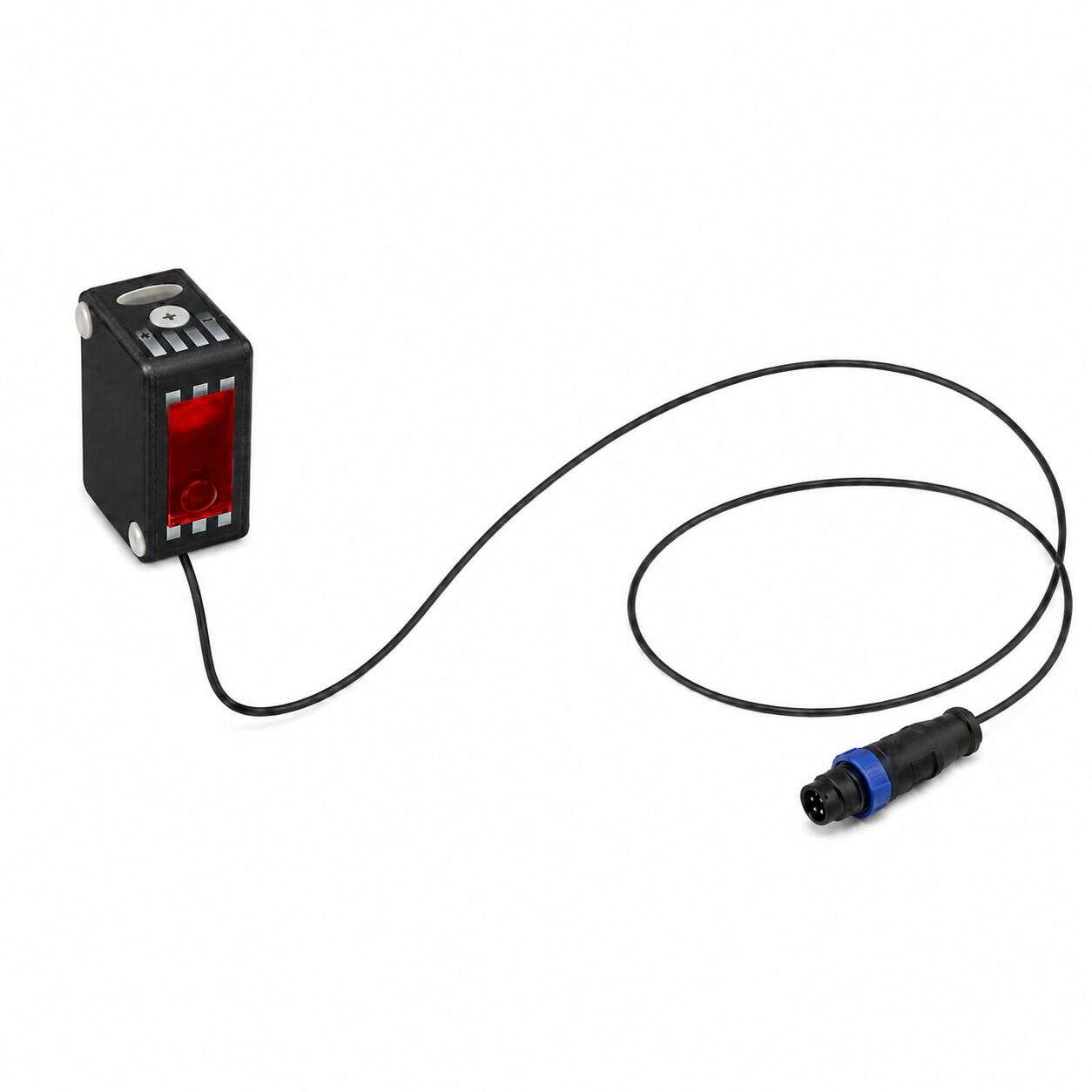
#6 Optischer Sensor
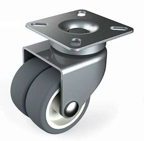
#7 Doppelrad-Lenkrolle
Qualifikationen und Berichte
O-Belt Powered Roller Conveyor Qualifications and Reports
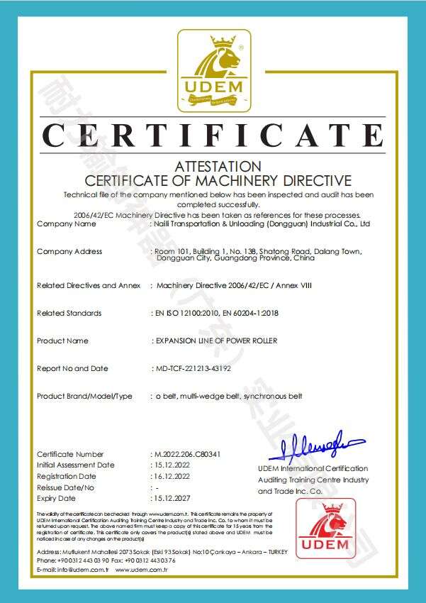
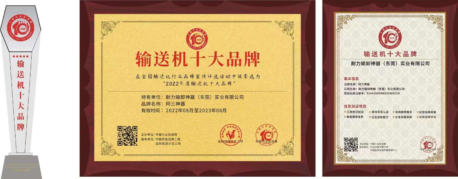
Sehen Sie sich die Zertifikate, Prüfberichte und Patenturkunden zu diesem Produkt an, um die Qualifikationen und die technische Grundlage leichter überprüfen zu können.
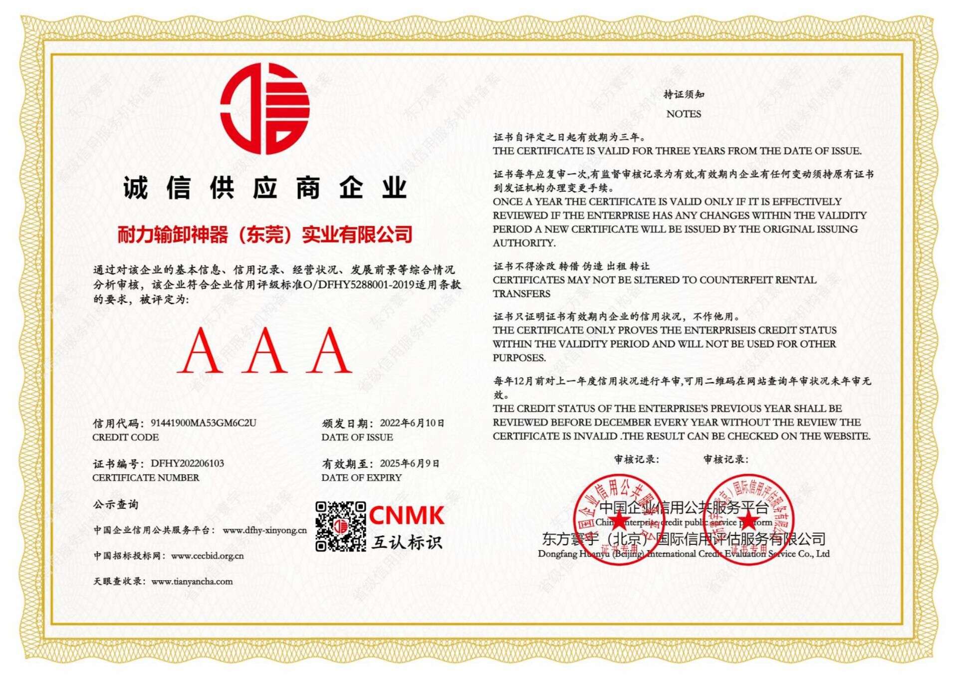
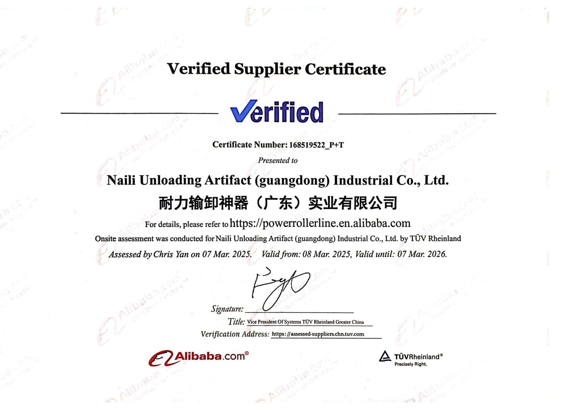
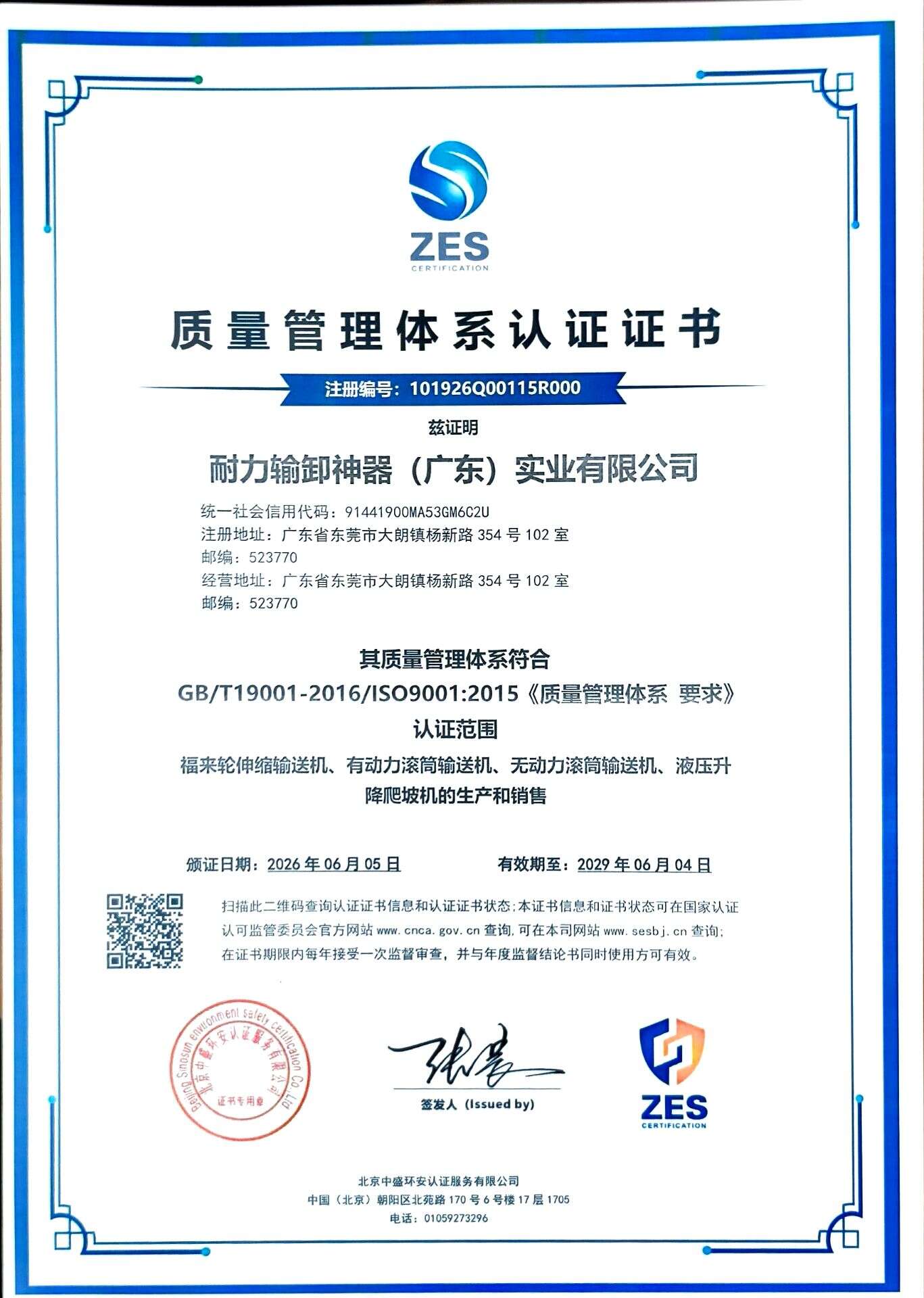
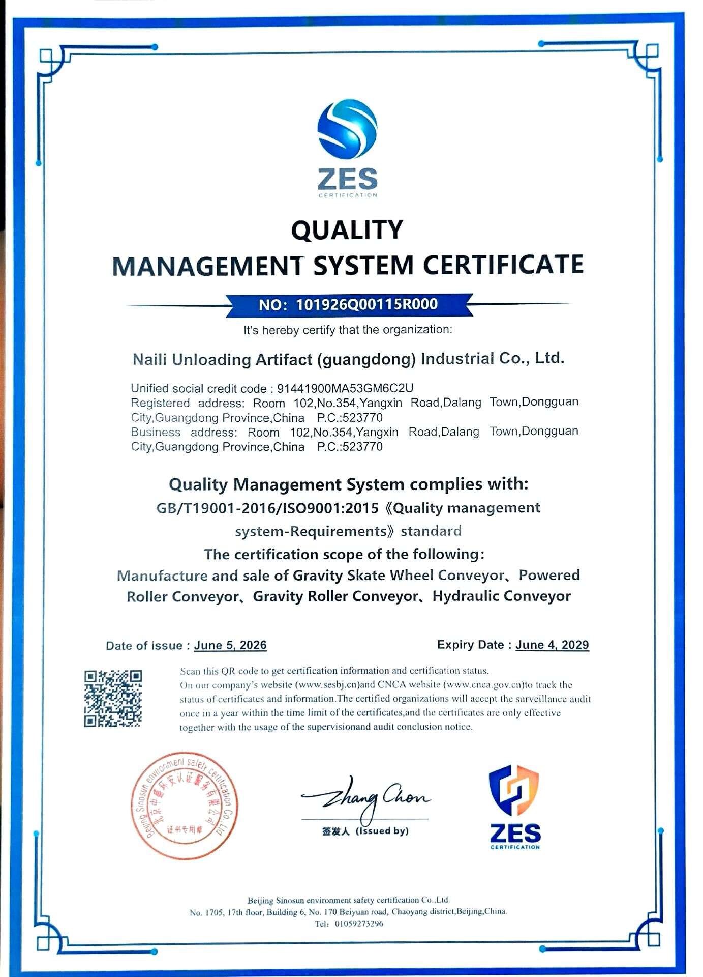
Zertifikate
Echte Fotos und Videos
O-Belt Powered Roller Conveyor Product Images
Sehen Sie sich die Anlagenstruktur, den Status vor Ort und betriebliche Details anhand von Fotogalerien und Videos an.
Echte Fotos und Videos
O-Belt Powered Roller Conveyor Case Videos
Sehen Sie sich die Anlagenstruktur, den Status vor Ort und betriebliche Details anhand von Fotogalerien und Videos an.
Echte Fotos und Videos
Videos zur Produktanleitung
Verschaffen Sie sich mithilfe von Videos zur Auswahl, Installation und Nutzung einen schnellen Überblick über die Konfiguration und die grundlegenden Bedienungsaspekte dieses Produkts.
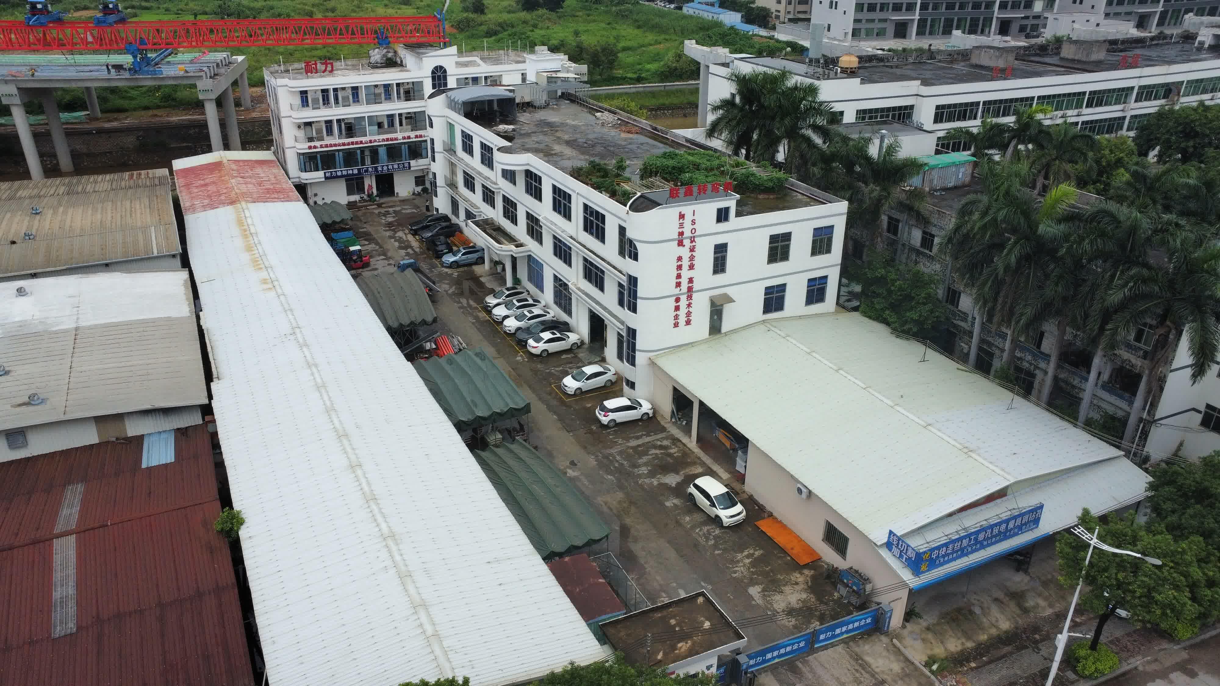
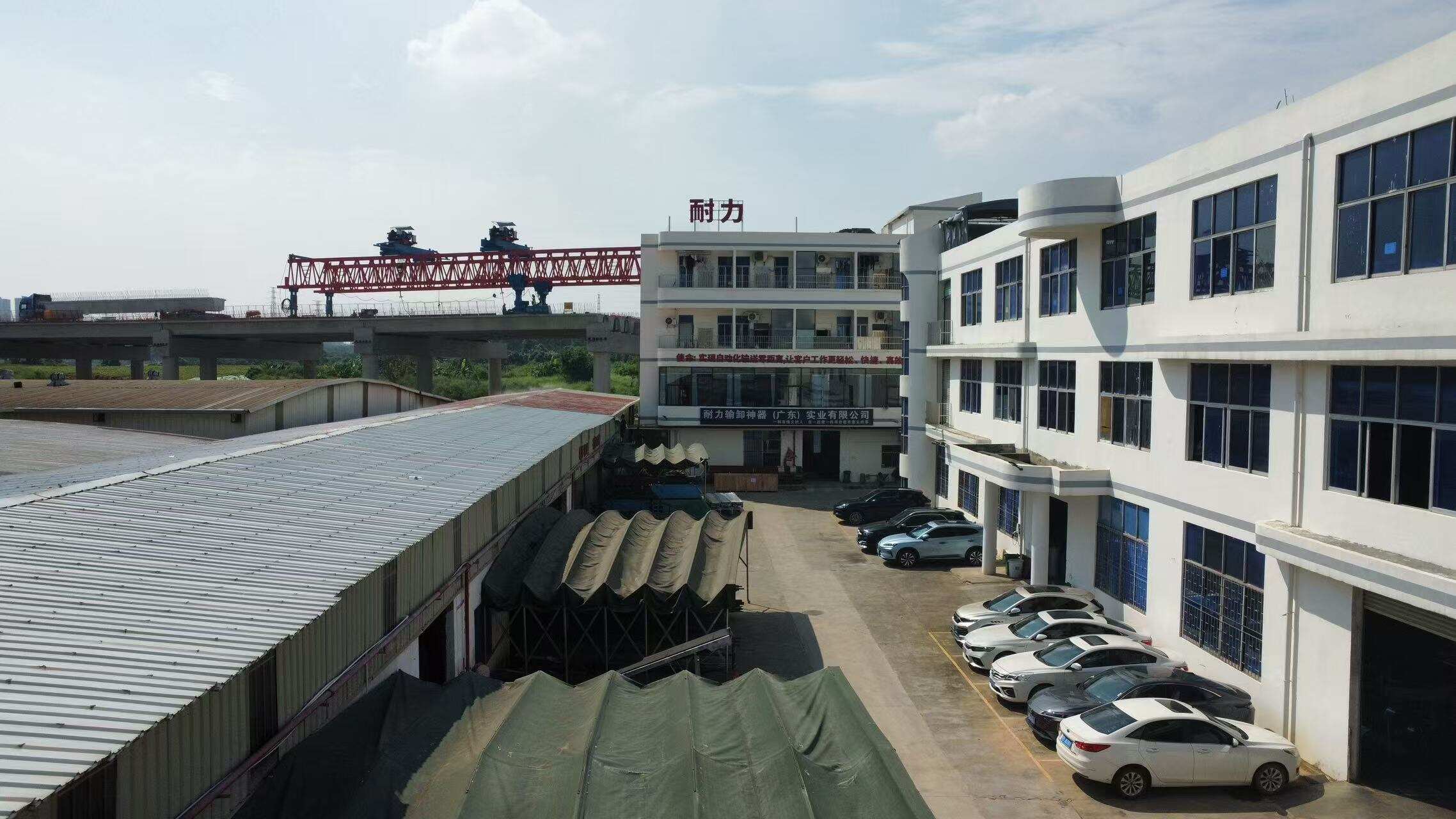
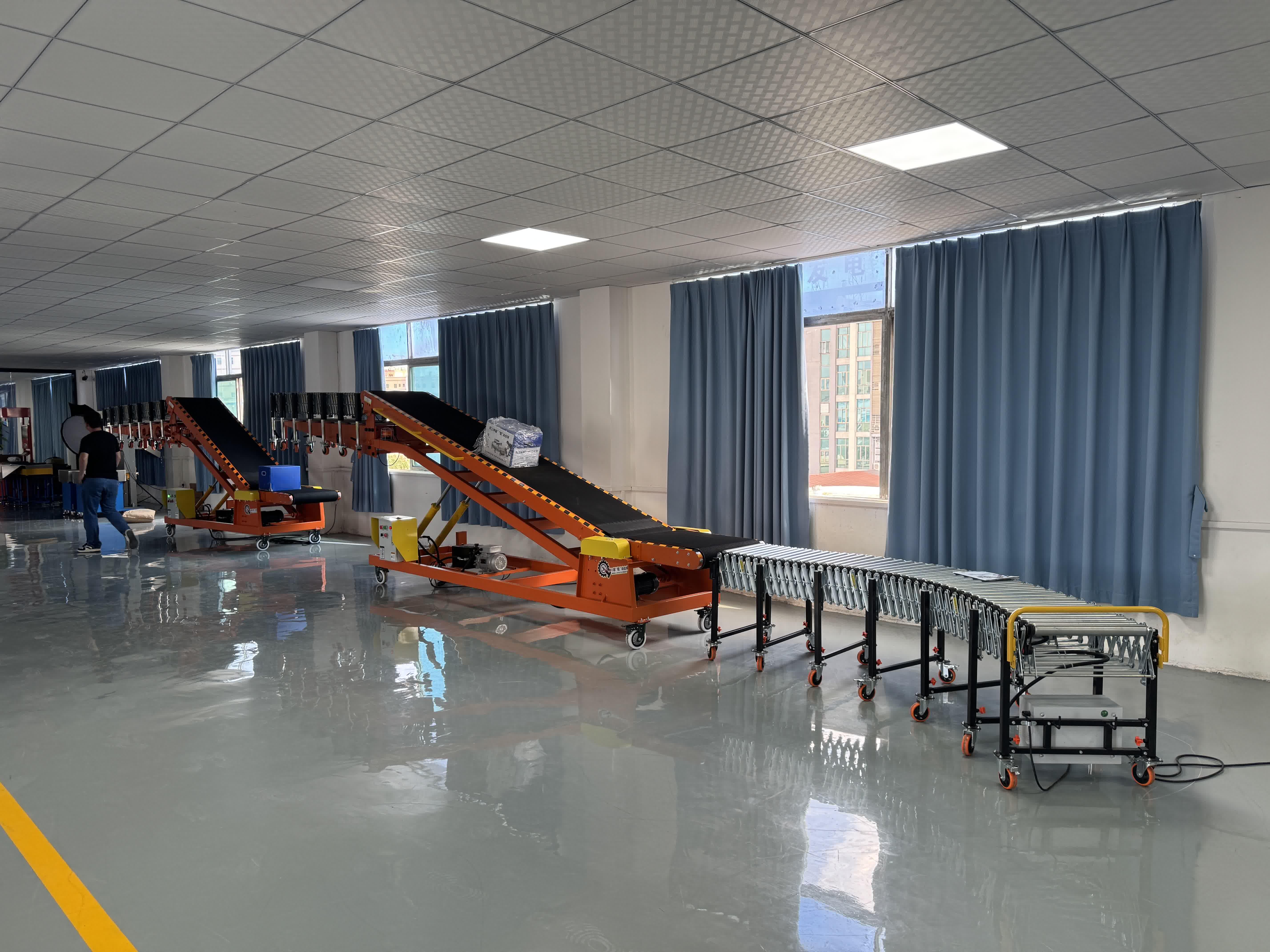
Werksstärke
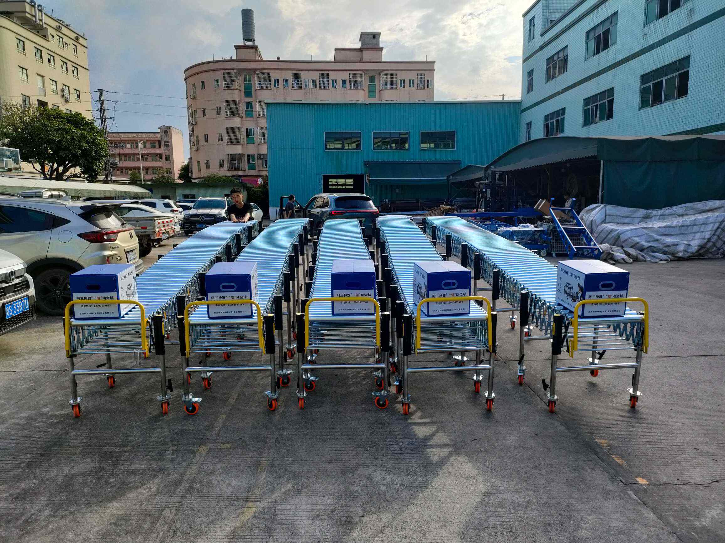
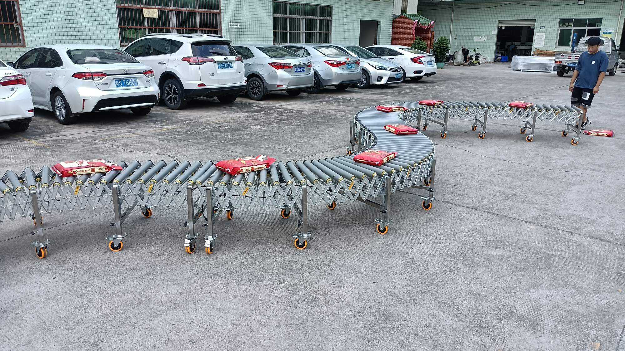
Erfahren Sie anhand von echten Fotos und Videos mehr über die Produktionsanlagen, die Werkstattumgebung, die Verarbeitungskapazität und die Qualitätskontrolle.
Bild
Bilder aus der Fabrik 4
Bild
Bild 1 aus der Fabrik
Bild
Fabrikbild 2
Bild
Fabrikbild 3
Bild
Hauptbild der Fabrik
Technische Daten
Spezifikationen und technische Daten
Hier können Sie die wichtigsten Parameter, strukturierte Spezifikationen und Materialien zum Herunterladen nach Modell anzeigen.
O-Belt Powered Roller Conveyor Technical Specifications
PRC-O-1.5
The O-belt Powered Roller Conveyor mainly solves the issues of horizontal conveying and routing between warehouse interiors, stocking areas, sorting areas, and loading/unloading areas. It is suitable for cartons, rolls, metal drums, plastic drums, and other goods with relatively stable shapes; it is easier to judge when the weight of each item is within 40 kg. Before purchase, first verify 4 boundary conditions: whether the bottom surface of the goods is suitable for roller passage, the effective width required on site, the footprint after full extension and after retraction, and whether the front and rear sections connect to manual handling, floor roller lines, or other conveying equipment.
Geltende Standort- und Ladungsgrenzen
This model is driven by an O-belt and is suitable for horizontal conveying in warehouses, factories, and logistics sites. Clearly defined cargo types include metal drums, plastic drums, rolls, and cartons, with each item weighing no more than 40 kg. If the bottom of the cargo is too soft, has discontinuous contact on the underside, has a high center of gravity, or has protruding shapes, the roller spacing, guiding method, and running stability must be confirmed first.
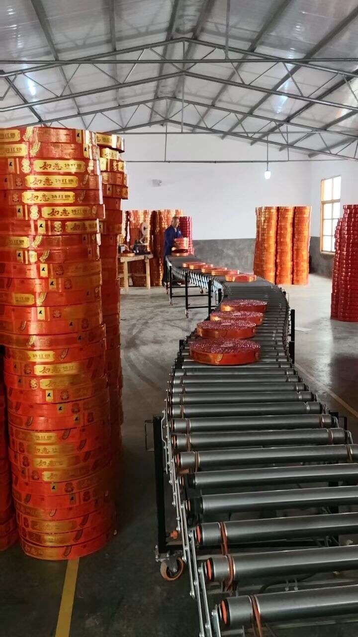
During on-site assessment, focus on the following items:
| Bedingungen vor Ort | Bewertung | Empfohlene Maßnahme |
|---|---|---|
| Mainly cartons, rolls, and drum-type goods, with a relatively complete bottom surface | Geeignet für Rollenförderer | Select the model according to the effective width and load capacity per meter first |
| Each item weighs within 40 kg | Falls within the covered cargo range | Then verify the accumulated weight per unit length |
| The cargo will pass through the curved section | The turning radius and cargo shape must be checked at the same time | First confirm the longest side, shortest side, and passing posture |
| The aisle needs to go around pillars, run along walls, or avoid workstations | Extendable and bendable layout is meaningful | First confirm the parking position after retraction and the operating range after extension |
| The bottom surface of the cargo is uneven, prone to sinking, or subject to compression | Engineering confirmation required | Reconfirm the roller type or conveying method |
If the site needs to cross floors, lift to the second level, or convey from the ground to a high-level workstation, this type of horizontal powered roller line on this page usually needs to be connected in segments with lifting equipment; see Vertikalförderer vom Typ C, 50 kg/m oder 50 kg/m Vertikalförderer vom Typ Z.
So lesen Sie die wichtigsten Parameter ab
For this type of equipment, there is no need to look at every dimension first; just confirm the parameters that have the greatest impact on the site. This model group is currently specified for 1.5 m per section models, and the main parameters are as follows:
| Parameter | Auswirkungen auf die Modellauswahl | So führen Sie die Bestätigung vor Ort durch |
|---|---|---|
| Base length A: 525 mm | Affects the footprint and parking space when retracted | Check the length of the parking area when the equipment is idle |
| Fully extended length C: 1500 mm | Affects the coverage distance after a single section is extended | Measure the straight or curved distance between the channel and the workstations |
| Extension ratio: 1: 2.86 | Affects the extension and retraction range | Check both the operating length and the non-operating length |
| Nutzbreite: 500/600/800/1000 mm | Determines the maximum width of goods that can pass through | Confirm based on the maximum bottom dimensions of the goods and the clearance needed for manual straightening |
| Load capacity: 80 kg/m | Determines the maximum load per unit length | Estimate based on the spacing between goods, stacking method, and the number of items on the conveyor at the same time |
| Geschwindigkeit: 0,3–40 m/min | Determines the conveying rhythm and how it works with manual handling | Confirm according to the pace of packing, sorting, and receiving |
Also note two points:
- The per-piece goods limit and the load per meter are two different concepts. The per-piece weight of goods covered on this page is within 40 kg, while the entire conveyor line must also meet the 80 kg/m load limit.
- If the on-site plan involves multiple sections combined together, the total extended length, total retracted length, and the number of gear motors must be confirmed based on the number of sections. It is not advisable to extrapolate the entire line layout directly from single-section data.
Turning and Extension Layout Confirmation
One practical value of this model is that on-site aisles are not always straight. The equipment is extendable and turnable, making it suitable for avoiding racks, columns, doorways, and temporary stacking areas, and it can also be retracted when not in use.
When arranging turning and extension, it is recommended to confirm in the following order:
- First confirm whether the starting point and end point of the operation are fixed.
- Then confirm whether the middle aisle needs to be routed around obstacles.
- Next, confirm the maximum distance that needs to be covered when fully extended.
- Finally, confirm whether the parking area after retraction will occupy the fire lane, forklift lane, or pedestrian passage.
If the goods pass through in a curved state, the key is not only to confirm that the equipment can turn, but also to check the width of the goods' bottom surface, length, and center of gravity position. When drums and rolled goods pass through curved sections, it is usually necessary to confirm whether manual straightening, positioning stops, or reduced-speed passage are required. The stand height can be adjusted manually, and the unit is equipped with swivel casters with foot-activated locking wheels, making it easy to move and position; after moving, lock it first before conveying.
How to Connect the Front and Rear Sections
O-type belt Powered Roller Conveyor is commonly used for connections between workshop interiors, warehouse aisles, and loading and unloading areas. There are usually three ways to arrange the front and rear sections:
- For manual loading and unloading: focus on confirming the operating platform height, operator position, and clearance on both sides.
- For connecting to a floor roller line: focus on confirming consistent width, consistent line height, and consistent cargo flow direction.
- For connecting to other conveying equipment: focus on confirming interface height, cycle time, and changes in cargo posture.
If the upstream or downstream process requires a longer in-warehouse horizontal conveying distance, you can also refer to the following model in the same Powered Roller Conveyor category: Rollenförderer mit Mehrrippenriemenantrieb; if the cargo is heavier and the drive method needs to be confirmed based on chain-drive principles, you can refer to Kettengetriebener Rollenförderer.
If there is a height difference between the truck body and the ground at the site, this unit usually handles the horizontal section outside the vehicle, while the height-difference section requires a separate incline conveyor. See Mittlerer Hydraulikförderer.
For related site applications, see Fireworks Warehouse O-Belt Roller Conveyor Solution.
How to distinguish between similar Powered Roller Conveyor models
Within the Powered Roller Conveyor category, first distinguish them by cargo form, conveying distance, and drive method:
- This model is mainly used for horizontal conveying of relatively stable cargo forms such as cartons, rolls, metal drums, and plastic drums, while also supporting extension, turning, and on-site movement.
- Rollenförderer mit Mehrrippenriemenantrieb It is suitable for scenarios that require a longer line layout, straight sections in warehouses, or combined conveying sections, where connection length and layout method are usually more critical.
- Kettengetriebener Rollenförderer It is suitable for working conditions that need to be confirmed based on a chain-drive structure, and when purchasing, more attention should be paid to drive segmentation, cargo weight, and line structure.
If the site mainly involves "moving, folding away, detouring, or temporary line changes, " this O-belt type is easier to judge; if the focus is on "long fixed lines, segmented structure, and heavy-duty drive, " then the comparison should focus on other Powered Roller Conveyor models in the same category. When a single item exceeds 40 kg or the unit load exceeds 80 kg/m, the load capacity and conveying method need to be confirmed again.
Bestätigung vor dem Kauf
When discussing a purchase, explain the following information clearly at once so the solution will be closer to the actual site:
| Anzugebende Informationen | Why it needs to be confirmed |
|---|---|
| Cargo type: cartons, rolls, metal drums, plastic drums | Determine the bottom contact method and passage stability |
| Maximum weight per item, longest side, minimum bottom dimensions | Determine effective width, roller passability, and turning posture |
| Required deployed length and folded storage length on site | Determine the number of sections, extension ratio, and floor space |
| Need a straight layout, a single bend, or multiple bends | Determine aisle compatibility and number of turns |
| Names, width, and height of upstream and downstream equipment | Determine interface position and connection method |
| Operating method: manual receiving, manual loading, or intermediate buffering | Determine speed range and operator position |
| Whether frequent movement is required | Determine caster layout, locking positions, and parking area |
FAQ:
1. Is it suitable for drums and coil-wound goods?
It is suitable for metal drums, plastic drums, and coil-wound goods, but the weight per item should be kept within 40 kg, and the stability of the bottom contact should be checked, especially the posture when passing through curved sections.
2. Which load-bearing conditions need to be confirmed?
First, the weight per item; second, the total weight per unit length. This model group has a clear load capacity of 80 kg/m. If multiple items are concentrated over a short distance, it needs to be checked again.
3. How should the effective width be selected?
It can be confirmed from 500/600/800/1000 mm. It is usually determined based on the maximum bottom dimensions of the cargo, with extra allowance for manual straightening and deviation correction.
4. What is most likely to be overlooked in a turning layout?
The easiest thing to overlook is the sweep space of the cargo outline in the curved section, as well as the parking area after retraction. On site, you should measure not only the aisle width, but also the clearance on the inside and outside of the curve.
5. What length information should be provided before purchase?
At minimum, provide whether you need a single section or a multi-section combination, the total deployed length during operation, and the allowed length when parked. For multi-section combinations, the total extended length, total retracted length, and the number of geared motors must be confirmed according to the final solution.